

 English
 中文简体
Industry News
Home / News / Industry News / Load Cell for Tank Weighing System: Selection, Sizing, Mounting and Setup Guide
Content
A 12,000-litre stainless mixing tank that reads 40 kg heavy after a hot clean-in-place cycle is almost never suffering from a bad indicator. In most tank and silo weighing projects the error is mechanical: a rigid pipe tying the vessel to the building steel, a check rod that binds once the tank grows 6 mm taller, or a load cell chosen with a capacity so large that a half-empty vessel never leaves the bottom of its measuring range.
The practical answer for a load cell for tank weighing system build is short. For a vertical tank or silo carried on three or four legs, use compression column load cells, one under each leg, sitting in self-aligning mounting assemblies. Size each cell so that the normal working load lands between roughly 25% and 60% of rated capacity. Restrain at least two legs against horizontal movement, and connect every pipe, hose, cable and sight glass to the vessel through something flexible. Then calibrate with real product rather than test weights alone.
That is the conclusion. The rest of this page explains the reasoning behind it, the arithmetic that decides the capacity number, and the failure modes that appear two or three years after startup, when nobody remembers how the anchor bolts were grouted.
A truck scale weighs a load that arrives, sits still and leaves. A process tank does the opposite. It is bolted to a structure, filled with hot or cold product, agitated, steamed, rinsed with caustic, and expected to return to the same zero every morning for a decade. Five forces work against that expectation, and only one of them is electrical.
A 4-metre tall carbon steel vessel heated from 20 degrees to 120 degrees Celsius grows by roughly 4.7 mm in height, and a similar amount in diameter. If the mounting plates are bolted flat to the floor with no allowance, that growth turns into a horizontal push on every load cell. Column load cells handle vertical force well and side force badly.
A single rigid inlet pipe with a flange can carry 200 kg or more of load straight past the sensors and into the building. The scale then reads low, and the error changes whenever the pipe temperature changes.
Agitators, blowers mounted on the tank top, screw conveyors and wind all introduce horizontal and oscillating forces. These do not usually break a load cell immediately. They nibble at repeatability until the batch records stop matching the flow meter.
If one concrete pier settles 1.5 mm more than the others, that leg can go into tension or lose contact completely. A load cell with a gap under it is not measuring anything.
A rule of thumb used by service engineers in the field is worth remembering: if a tank system loses more than about 0.1% of full scale per year in zero repeatability, inspect the mechanical interface before touching the electronics. Nine times out of ten the sensor is innocent.
Not every load cell shape belongs under a vessel. The table below summarizes the six families you will encounter in quotations, what they do well and where they go wrong.
| Load cell type | Typical capacity range | Best suited to | Main risk to manage |
|---|---|---|---|
| Column or canister compression | 5 t to 100 t | Vertical vessels on 3 or 4 legs | Side load if stay rods are missing |
| Digital column load cell | 10 t to 50 t | Multi-leg tanks needing corner diagnostics | Higher unit and cabling cost |
| Double-ended shear beam | 1 t to 20 t | Rectangular hoppers, two supports per beam | Needs a flat, level mounting surface |
| S-type tension cell | 100 kg to 5 t | Suspended or hanging hoppers and blenders | Swing and oscillation need dampers |
| Clamp-type or single-point | 5 kg to 500 kg | Day bins, dosing hoppers, filling heads | Limited capacity and stiff mounting |
| Bending beam | 5 kg to 1 t | Compact tank bases and small platforms | Sensitive to off-centre loading |
Almost every large vertical tank, silo and reactor leg lands on a column cell. The design is simple: a hardened steel or stainless cylinder in compression, with strain gauges bonded to the inner wall. Because the column is short and stiff, it deflects very little under load, which suits vessels where the structure must not move.
A digital column load cell performs the analogue-to-digital conversion inside the housing and sends a serial value outward. Each leg reports its own weight, so a technician can see which leg is dragging. On a four-leg vessel that is the difference between a two-hour diagnosis and a two-day one.
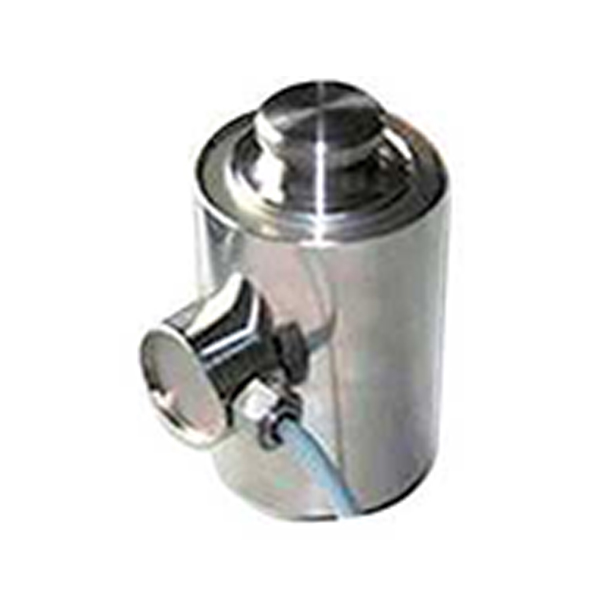 Column Type Digital Load CellThe column-type digital weighing sensor is designed for applications that require long-distance transmission and high stability. It supports a variety of specification...View Product →
Small stainless day bins on a filling line, dosing hoppers under a mixer, and compact blenders rarely justify column cells. A clamp-type metal sensor or a pair of shear beams gives adequate performance at lower cost, provided the loads stay centred and the mounting plate is machined flat. Above 500 kg per support point, move back to a compression column design.
Capacity selection is where most projects lose accuracy before the equipment is even ordered. The mistake is almost always the same: choosing a cell large enough for the theoretical worst case and forgetting that the vessel spends most of its life half full.
Take a jacketed mixer on four legs with the following load breakdown.
| Load component | Mass |
|---|---|
| Empty vessel, jacket and agitator | 2,500 kg |
| Product at maximum fill | 6,000 kg |
| Insulation, cladding, ladders, nozzles | 500 kg |
| Total static load | 9,000 kg |
| Load per leg across four supports | 2,250 kg |
| Design factor for uneven fill and agitation (1.4) | 3,150 kg |
| Selected rated capacity per cell | 5,000 kg |
With a 5,000 kg cell, the working point at full fill is 63% of rated capacity including the design factor, or about 45% of the raw rating without it. That is a healthy place to sit. Practical design factors for agitated or pneumatically filled vessels usually fall between 1.3 and 1.5; for a calm storage silo filled by gravity, 1.15 to 1.25 is often enough.
A load cell quoted at 0.02% of full scale is accurate to 0.02% of its rating, not of the load sitting on it. Put a 20,000 kg cell under a leg that normally carries 800 kg and the error term becomes 0.5% of the actual reading. Add a 500 kg dead weight from the vessel itself and the useful signal is buried. This is why a 750 kg batch on a vessel fitted with 20-tonne cells can wander by several kilograms while the same indicator on correctly sized cells holds within 200 g.
As a working target, keep the normal operating load between 25% and 60% of rated capacity, and make sure the minimum batch you intend to measure produces a readable change. If the smallest batch is 5% of full capacity, accept that the resolution will be coarse.
Outdoor silos see wind pressure that can exceed the product load on the leeward leg. Do not solve this by doubling the cell rating. Solve it with check rods and a structural frame that carries the horizontal force directly to the foundation, leaving the load cell to see only vertical load.
Hardware decisions made on site during installation decide whether the system works. The following points come up in nearly every tank project.
Three-leg vessels are self-stabilising under load and are easier to set up, which is why small and medium tanks often use three supports. Four-leg vessels need more care because the structure is statically indeterminate: one leg will always carry more or less than its share unless the frame is stiff and the mounting heights are matched.
An analogue strain gauge load cell produces roughly 2 mV per volt of excitation at rated capacity. With 10 V excitation that is a 20 mV full-scale signal. On a tank running at 40% of capacity, the live signal is closer to 8 mV, and the resolution you need may be 1 part in 20,000 of that. Long runs near variable-frequency drives, welding cables and motors will not respect such a small number.
A digital junction box helps by summing and digitising at the vessel, but the classic weakness remains: the analogue section still sits in the field. Digital load cells move the conversion into each cell, so the cable carries a robust serial signal rather than millivolts. Runs of well over 100 metres become realistic, and the reading no longer changes when a forklift drives past. If long cable distance is a concern in your layout, the engineering behind long-distance data transmission from column-type digital load cells is worth reading before the cable schedule is fixed.
Either way, keep these practices: run load cell cable in its own conduit, separate from power and drive cables; earth the shield at one end only; and use a junction box with a proper gasket and a drain, because a junction box that fills with condensate is the single most common cause of drifting tank weights in humid plants.
Tanks that hold solvents, fine powders or volatile intermediates need a different hardware conversation. The vessel itself becomes a potential ignition source through static discharge, and the load cell cable is an electrical path into that area.
Explosion-proof load cells use a sealed, robust housing and internal circuit protection so that a fault cannot release enough energy to ignite the surrounding atmosphere. Intrinsically safe instruments limit the energy delivered to the sensor circuit in the first place. The two approaches are often combined in a tank installation: protected cells in the field, a safe-area indicator fed through an isolating barrier.
For a solvent-handling reactor, also confirm bonding and earthing of the vessel and the mounting frame. A load cell assembly that isolates the tank electrically can leave it floating, which is a problem in its own right.
 Explosion-proof sensorsExplosion-proof sensors are designed for hazardous environments and are widely used in places containing explosive gases, such as petrochemical, coal gas, pharmaceutic...View Product →
Food, dairy and pharmaceutical vessels are hosed down daily. Choose stainless housings, fully welded cable entries and connectors rated for the cleaning chemicals in use. A load cell rated for splash protection but installed with a standard cable gland will absorb water through the gland, not the housing.
Fertiliser, brine, acids and coastal air attack mild steel hardware long before they attack the sensor. Specify stainless or coated mounting plates, and remember that a load cell operating at 120 degrees Celsius ambient behaves differently from one at 20 degrees. Temperature compensation matters more on hot vessels than most buyers expect.
The indicator or weighing terminal does more work than most people assume. Beyond displaying a number, it sums the legs, applies the dead load subtraction, filters out agitation noise, and passes the result to a PLC, a batch controller or a historian.
For plants that want inventory visibility across several silos, an IoT weighing instrument with Ethernet communication removes the extra data-collection hardware and keeps the weight data in one place.
Power quality is part of instrumentation too. A brief dip during a compressor start can drop a batch record or push an indicator into an error state. In plants with unstable supply, a regulated supply or an uninterruptible power supply dedicated to the weighing circuit costs far less than a spoiled batch.
Commissioning order matters. Doing these steps out of sequence usually means repeating several of them.
If the vessel is agitated during calibration, the reading will never settle. Calibrate static, then tune the indicator filter for the agitated condition afterwards.
Most tank weighing complaints follow a handful of patterns. The table below is the field sequence worth following before ordering spare parts.
| Symptom | Likely cause | Check first |
|---|---|---|
| Weight climbs after a hot fill | Thermal growth through rigid pipework | Flexible hose condition and freedom of the vessel |
| One leg reads far from the others | Mechanical binding or a failed cell | Swap the suspect cell to another position |
| Random drift in humid weather | Condensation in junction box or connector | Gasket, drain and cable gland sealing |
| Reading jumps when a drive starts | Electrical noise on the signal cable | Cable routing and shield earthing |
| Zero shifts after cleaning | Water ingress or product build-up on a leg | Physical inspection of every assembly |
| Weight correct at full, wrong when half empty | Non-linearity from oversized cells or bad span calibration | Three-point calibration record |
A tank weighing system is not commissioned once and forgotten. Vessels settle, gaskets compress, check rods get knocked by a forklift, and product residue builds up on a mounting plate until the readings stop making sense.
Reasonable intervals for a process vessel are a zero and repeatability check every three months, a span verification every six to twelve months, and a full mechanical inspection of every leg annually. Plants working under tight batch tolerances often shorten the zero check to monthly. A structured preventive maintenance programme for weighing systems pays for itself the first time it catches a binding check rod before a batch is rejected.
Keep a simple log per vessel: date, ambient temperature, empty reading, test mass result, and any mechanical work done. After two years, that log tells you more about system health than any single measurement can.
Suppliers who ask for the empty weight, the leg arrangement and the piping layout before quoting are usually the ones whose systems hold their calibration. A quote that lists only a capacity and a price is a starting point, not a design.
Three legs suit most small and medium vertical vessels because the support is statically determinate and stable. Four legs are common on larger tanks and on rectangular vessels, but they demand a stiff frame, matched mounting heights and careful check rod adjustment. A few very large silos use six or eight points, in which case per-leg diagnostics become close to essential.
It is possible in a clean electrical environment, but it is fragile. An 8 mV live signal over 80 metres next to pump drives will pick up noise. A digital junction box closer to the vessel, or digital load cells that transmit a serial value, removes most of that risk.
On a well-installed process vessel with correctly sized cells, a working accuracy of 0.1% to 0.5% of the live load is achievable. Storage silos with fewer mechanical complications often do better. Systems quoted at 0.02% usually refer to the load cell rating under laboratory conditions, not to the installed vessel.
No, but the tank must be empty and disconnected from rigid services. The usual sequence is to lift one leg at a time with hydraulic jacks, insert the mounting assembly and cell, then grout and lower. Plan for at least a full day on a four-leg vessel, plus time for the flexible pipework modifications.
Agitation creates a dynamic force that the indicator averages over time. If the reading is unstable rather than slightly offset, increase the filter or average the weight over a longer window. If the average itself shifts, the agitator is applying a real force to the vessel through its mounting or through a rigid shaft seal, and the mechanical installation needs attention.
Yes, but pressurised vessels introduce an upward or downward force on the shell that varies with internal pressure. If that force is carried by rigid pipework or a fixed support, it will appear as a false weight change. The fix is to let the vessel float vertically on its load cells and to connect every service through a flexible element that can absorb both thermal and pressure movement.
There is no fixed calendar life. A properly protected column cell in a clean environment can run for fifteen years or more. Cells in wet, corrosive or heavily vibrating service may need replacement in five to eight years. Replace on evidence: failed insulation resistance, unstable zero, or a leg that behaves differently from the others after mechanical checks.
Use the load cell cable specified by the equipment supplier, usually a shielded twisted-pair construction with a drain wire. Run it in separate conduit from power cables, avoid sharing a tray with variable-frequency drive wiring, and earth the shield at one end only.
Tank and silo weighing rewards preparation more than any other branch of industrial weighing. The electronics are rarely the hard part. What decides whether the batch records agree with the flow meter next year is whether someone calculated the load per leg properly, whether the piping was made flexible, whether the check rods were set with a little freedom, and whether the mounting plates were grouted level on the day the concrete was still workable.
Get those four things right and a mid-range column load cell will outperform an expensive oversized one installed badly. Get them wrong and no indicator, no filter setting and no recalibration will fix a vessel that is fighting its own structure.
Copyright © Ningbo Jiuding Weighing Equipment Co., Ltd.