 English
 中文简体
中文简体
Industry News
How Load Cells Work: The Science Behind Weighbridge Accuracy
Content
- 1 How a Load Cell Works: The Short Answer
- 2 The Strain Gauge: Core of Every Load Cell
- 3 Load Cell Types Used in Weighbridges
- 4 From Raw Signal to Weight Reading: The Signal Path in a Weighbridge
- 5 Key Load Cell Specifications and What They Mean for Weighbridge Performance
- 6 Analog vs. Digital Load Cells in Weighbridge Systems
- 7 How Load Cells Are Mounted in a Weighbridge
- 8 Common Load Cell Failure Modes in Weighbridges
- 9 Calibration: Connecting Load Cell Physics to Legal Accuracy
- 10 Practical Tips for Maximising Load Cell Lifespan in Weighbridge Applications
- 11 How Weighbridge Accuracy Is Affected by Load Cell Count and Placement
How a Load Cell Works: The Short Answer
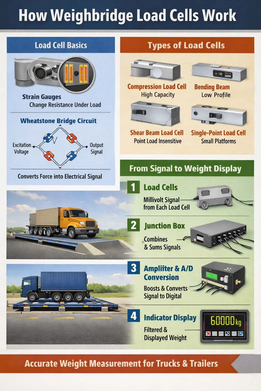
A load cell converts mechanical force—weight—into an electrical signal. Inside every load cell is a metal element that deforms slightly under load. Bonded to that element are strain gauges: thin resistive foils whose electrical resistance changes as they stretch or compress. That change in resistance produces a measurable voltage output proportional to the applied force. In a weighbridge, multiple load cells are placed under the deck, and their combined electrical signals are processed by an indicator or junction box to display a weight reading.
That is the core mechanism. Everything else—hermetic sealing, temperature compensation, overload protection, digital output—is engineering built around that fundamental principle. Understanding the details matters because load cell selection, installation, and maintenance directly determine how accurately and reliably a weighbridge performs over years of operation.
The Strain Gauge: Core of Every Load Cell
The strain gauge is the sensing element that makes load cell technology possible. It consists of a fine metallic foil pattern—typically a nickel-chromium alloy—bonded with adhesive to the surface of an elastic metal body, usually high-grade alloy steel or stainless steel. When the metal body deforms under weight, the foil deforms with it. This changes the foil's electrical resistance according to a relationship described by the gauge factor (GF).
The gauge factor for most metallic strain gauges is approximately 2.0, meaning a 0.1% strain produces a 0.2% change in resistance. For a standard 350-ohm strain gauge, that translates to a resistance change of about 0.7 ohms—a tiny value that requires careful circuit design to measure accurately.
The Wheatstone Bridge Circuit
Load cells use four strain gauges arranged in a Wheatstone bridge configuration. Two gauges are placed in tension (they elongate under load) and two in compression (they shorten under load). This arrangement provides several critical advantages:
- The output signal is doubled compared to using a single gauge, improving sensitivity.
- Temperature effects cancel out because all four gauges experience the same thermal environment.
- Non-linearity errors are reduced through the opposing gauge arrangement.
- The bridge produces zero output at zero load (a null output), making the signal easier to process.
A standard excitation voltage of 5 to 15 volts DC is applied across the bridge. At rated capacity, the bridge produces a millivolt-level output—typically 2 mV/V, meaning a 10V excitation produces 20 mV at full load. This signal is then amplified and processed.
Load Cell Types Used in Weighbridges
Not all load cells share the same geometry. The internal shape of the elastic element determines how it deforms, which influences accuracy, capacity range, and suitability for different weighbridge configurations.
Compression Load Cells
These are the most common type found in pit-mounted and surface-mounted weighbridges. They are designed to bear load in a single axis—straight down—and are typically cylindrical or pancake-shaped. Compression cells used in truck scales handle capacities from 50 tonnes to over 150 tonnes per cell, with six to twelve cells commonly supporting a full weighbridge deck. They are robust, straightforward to install, and handle side loads reasonably well when fitted with proper mounting hardware.
Bending Beam Load Cells
Bending beam cells work on a cantilever or double-ended beam principle. Load is applied at one or two points along a beam fixed at the other end, causing it to bend. Strain gauges placed at the maximum bending moment location capture this deformation. These cells are popular in low-profile platform scales and certain portable weighbridge designs because they can be installed in a very shallow deck profile. They are typically used for capacities under 20 tonnes per cell.
Shear Beam Load Cells
Shear beam cells measure shear stress rather than bending or direct compression. The strain gauges are oriented at 45 degrees to the beam axis to capture maximum shear strain. This design is highly insensitive to the point of load application—a significant advantage in weighbridge applications where a vehicle's axle load may not land at an exact position. Shear beams offer excellent accuracy, typically achieving OIML Class C3 or better, and are widely used in both portable axle weighers and permanent weighbridge installations.
Single-Point Load Cells
Single-point cells are engineered to give accurate readings regardless of where the load is placed on a platform—within limits. They are primarily used in smaller platform scales and are rarely found in full-size truck weighbridges. However, they appear in some axle pad weighers used for quick roadside enforcement checks.
| Load Cell Type | Typical Capacity Range | Common Weighbridge Use | Key Advantage |
|---|---|---|---|
| Compression | 50–150 t per cell | Pit-mounted truck scales | High capacity, robust |
| Bending Beam | Up to 20 t per cell | Low-profile platforms | Compact installation |
| Shear Beam | 5–50 t per cell | Portable and fixed axle weighers | Point-of-load insensitivity |
| Single-Point | Up to 5 t | Axle pad weighers | Uniform response across platform |
From Raw Signal to Weight Reading: The Signal Path in a Weighbridge
Understanding how a load cell works in isolation is only part of the picture. In a weighbridge installation, multiple load cells work together, and their signals go through several processing stages before a weight value appears on the display.
Step 1: Individual Cell Output
Each load cell beneath the weighbridge deck produces a millivolt-level signal proportional to the force it is carrying. Because the load from a vehicle is never perfectly centered, individual cells carry unequal shares. A 60-tonne truck parked asymmetrically might impose 12 tonnes on one corner cell and 8 tonnes on another.
Step 2: Junction Box and Signal Summing
All individual cell cables run to a junction box (also called a summing box). Inside, the signals are combined—either passively through resistive summing networks or actively through amplification. Passive summing junction boxes use trim resistors to adjust for differences in cell sensitivity, ensuring that a 1-tonne load on any single cell produces an identical contribution to the summed output. This calibration step is critical: without it, the position of the load on the weighbridge deck would influence the final reading.
Step 3: Amplification and Analog-to-Digital Conversion
The summed millivolt signal—still very small—travels to the weight indicator. Inside, a precision instrumentation amplifier boosts the signal, typically to a range of 0–10 volts. An analog-to-digital converter (ADC) then samples the amplified signal. Modern weighbridge indicators use 24-bit ADCs, which provide over 16 million discrete steps across the measurement range. This resolution is far finer than the legally required display increment, providing a stable and noise-resistant reading.
Step 4: Digital Filtering and Display
Raw ADC data is noisy. Wind loading, vehicle vibration, and electrical interference all cause rapid fluctuations. The indicator's microprocessor applies digital filtering algorithms—often configurable averaging or frequency-based filters—to extract a stable weight value. The final displayed value is rounded to the approved scale interval, which for legal-for-trade weighbridges is typically 20 kg for a 60-tonne scale.
Key Load Cell Specifications and What They Mean for Weighbridge Performance
When selecting load cells for a weighbridge, the datasheet numbers directly predict measurement quality. Here is what each specification actually means in practice.
Rated Capacity (Emax)
The maximum load the cell is designed to measure accurately. For safety, load cells are also rated for a safe overload—typically 150% of rated capacity—and an ultimate overload before permanent damage, usually 300%. A weighbridge handling 60-tonne gross vehicle weights supported by six cells needs cells rated for at least 15 tonnes each when load distribution is factored in, plus sufficient overload margin for dynamic loading during vehicle entry.
Accuracy Class (nmax)
OIML (International Organization of Legal Metrology) classifies load cells from Class A (highest accuracy) to Class D (lowest). Weighbridge load cells are typically Class C3 or C4, where the number indicates the maximum number of verification intervals—3,000 or 4,000 respectively. A C3 load cell used in a 60-tonne weighbridge can support a display increment of 60,000 kg ÷ 3,000 = 20 kg, which aligns with standard weighbridge requirements.
Combined Error
This specification combines non-linearity and hysteresis errors into a single value, usually expressed as a percentage of rated output. For a C3 load cell, the combined error is typically ±0.023% of rated output or better. On a 20-tonne capacity cell producing 2 mV/V at full load, this corresponds to an error of less than 0.9 microvolt—an extraordinarily small value that requires careful shielding and wiring practices to preserve through the signal chain.
Temperature Coefficients
Load cells used in outdoor weighbridge installations face substantial temperature swings. Two temperature coefficients matter:
- TK Zero: The change in zero output per degree of temperature change, typically specified as less than 0.02% of rated output per 10°C.
- TK Span: The change in sensitivity per degree, typically less than 0.008% per 10°C for quality load cells.
In an outdoor weighbridge operating from -10°C to +50°C—a 60-degree range—a cell with TK Span of 0.008%/10°C would experience a span shift of 0.048%. On a 60-tonne scale, that is a 29 kg drift attributable to temperature alone. This is why weighbridge calibration is always performed at operating temperature, and why periodic re-verification is legally required.
Ingress Protection (IP Rating)
Weighbridge load cells are permanently installed outdoors, often in pit environments subject to flooding, mud, and pressure washing. The minimum acceptable IP rating for weighbridge load cells is IP67 (dust-tight and withstands temporary immersion to 1 meter). Many installations specify IP68 or IP69K, the latter rating permitting high-pressure, high-temperature water jets—relevant for sites that clean the weighbridge deck regularly.
Analog vs. Digital Load Cells in Weighbridge Systems
Traditional load cells output an analog millivolt signal. Over the past two decades, digital load cells—which integrate an ADC and microprocessor directly inside the load cell body—have become increasingly common in weighbridge installations. The difference is significant in practical terms.
Analog Load Cell Systems
Analog cells are simpler, less expensive, and compatible with virtually any weight indicator on the market. Their millivolt signals are vulnerable to electromagnetic interference (EMI) over long cable runs—a real concern on large industrial sites with heavy machinery. The maximum practical cable run before signal degradation becomes problematic is approximately 100 to 150 metres with standard shielded cable.
Digital Load Cell Systems
Digital load cells convert the strain gauge signal to a digital value inside the cell housing and transmit the data via a serial bus—typically RS-485 or CAN bus. Key advantages include:
- Immunity to EMI over long cable runs, with reliable transmission over 500 metres or more.
- Individual cell diagnostics—the indicator can identify which specific cell has a problem, rather than just detecting a system fault.
- Automatic temperature compensation performed inside each cell using its own temperature sensor.
- Simplified trimming and calibration through software rather than resistor adjustment.
The trade-off is cost—digital load cells are considerably more expensive—and vendor lock-in, since cells from different manufacturers often use incompatible communication protocols.
How Load Cells Are Mounted in a Weighbridge
Correct mounting is as important as cell quality. A perfectly specified load cell installed incorrectly will give inaccurate and unstable readings. Weighbridge load cell mounting systems must accomplish several things simultaneously.
Transmitting Vertical Force While Rejecting Side Loads
Load cells are designed to measure force in one axis. Side loads—caused by vehicle braking, thermal expansion of the deck, or deck misalignment—introduce error and accelerate fatigue. Mounting assemblies use rocker pins, load buttons, or self-aligning load cell bases to ensure that off-axis forces are mechanically rejected. A rocker pin mounting allows the cell to tilt slightly in any direction, transferring only the vertical component of any applied force to the sensing element.
Accommodating Thermal Expansion
A steel weighbridge deck 18 metres long will expand approximately 10 mm between winter and summer temperatures in a temperate climate (using a thermal expansion coefficient of approximately 11.7 × 10⁻⁶ /°C and a 50°C temperature range). Mounting hardware must allow this movement without binding. Fixed-end and free-end mounting configurations address this by fixing the deck at one end and allowing constrained sliding movement at the other, preventing the thermal expansion from being interpreted as a load change.
Preventing Uplift
Some load cell mounting designs use tie-down bolts or retaining clips to prevent the deck from lifting off the cells during off-center loading. Without uplift restraint, an eccentric load near one end of a weighbridge could cause the opposite end to rise, taking cells off load and introducing a significant error. Check rod assemblies that limit upward deck movement to 2–3 mm are a standard part of quality weighbridge installations.
Common Load Cell Failure Modes in Weighbridges
Load cells are robust but not indestructible. Knowing how they fail helps maintenance teams identify problems before they cause significant weighing errors or complete system failures.
Moisture Ingress
Even IP68-rated cells can be compromised if cable entry points are damaged, if cable connectors are not properly sealed, or if the cell body is physically cracked. Moisture reaching the strain gauges causes corrosion of the foil, changes in adhesive properties, and ultimately electrical leakage between bridge arms. The symptom is typically a gradual drift in zero reading and increased instability. Checking insulation resistance between bridge circuits and the cell body (should exceed 5,000 MΩ on a healthy cell) is a standard diagnostic step.
Overload and Fatigue
A single severe overload—from a vehicle striking the deck at speed, or from a crane landing a heavy load unexpectedly—can plastically deform the elastic element. Once deformed, the cell's zero point shifts permanently and cannot be recalibrated away. Fatigue accumulates over millions of load cycles; most quality weighbridge cells are rated for 10 million or more cycles at rated capacity, but shock loading and overloading dramatically reduce fatigue life.
Cable Damage
Load cell cables run in exposed locations beneath weighbridge decks. Rodent damage, repeated flexing from deck movement, and physical crushing from debris are common causes of cable failure. A damaged shield or partial break in a signal conductor introduces noise, offset errors, or complete signal loss. Cable conduit protection and regular visual inspection are simple preventive measures that extend system life.
Corrosion of Mounting Hardware
Stainless steel load cell bodies are corrosion-resistant, but the surrounding mild steel mounting hardware—load cell bases, check rods, mounting bolts—is not. Corroded hardware can seize up, prevent the necessary small movements during thermal expansion, and introduce side forces on the load cell. An annual inspection and lubrication schedule for mounting hardware is a minimum maintenance requirement.
Calibration: Connecting Load Cell Physics to Legal Accuracy
A load cell's output in millivolts is meaningless until it is calibrated against known reference weights. Calibration establishes the mathematical relationship between electrical output and displayed weight, and periodic re-calibration confirms that relationship has not drifted.
Deadweight Calibration
The gold standard for weighbridge calibration is loading the deck with certified test weights of known mass—typically Class M1 or F2 certified masses traceable to national standards. The indicator is adjusted so that the displayed reading matches the applied weight at multiple points across the full measurement range. For a 60-tonne weighbridge, calibration typically involves test loads at 0, 20%, 50%, and 100% of maximum capacity.
Substitute Weight Calibration
Transporting and handling sufficient test weights for a full-capacity calibration is expensive and logistically demanding. Substitute weight methods—using a hydraulic load cell reference device or a vehicle of verified weight—allow calibration checks at lower cost. These methods are accepted by many national weights and measures authorities for periodic verification between full deadweight calibrations, provided the initial calibration was performed with deadweights.
Legal Verification Requirements
Weighbridges used for trade—billing customers by weight, checking vehicle compliance, or fiscal measurement—must be periodically verified by an authorized inspection body. In the European Union, the Non-Automatic Weighing Instruments (NAWI) Directive sets maximum permissible errors (MPE) for trade weighbridges: ±0.5 scale intervals at initial verification and ±1 scale interval in service. Verification intervals vary by jurisdiction but are commonly 1 to 2 years.
Practical Tips for Maximising Load Cell Lifespan in Weighbridge Applications
Load cells in a well-maintained weighbridge should remain accurate for 10 to 20 years. Reaching that service life requires consistent attention to a few key areas.
- Enforce approach ramp speed limits. A 40-tonne truck hitting a deck edge at 20 km/h generates a dynamic impact factor of 1.3 to 1.5 or more—effectively applying 52 to 60 tonnes instantaneously. Speed ramps or speed signs limiting access to 5 km/h dramatically reduce dynamic loading.
- Keep the pit dry. Install sump pumps with automatic float switches in pit-type weighbridge installations. Standing water accelerates corrosion of mounting hardware and increases the risk of moisture ingress into cable connectors.
- Inspect cable conduits quarterly. Look for crushing, cracking, or displacement that exposes cables to mechanical damage. Replace damaged sections before cable failure causes inaccurate weighing or a complete system outage.
- Log corner readings regularly. Most modern weighbridge indicators can display individual cell readings. Recording these periodically creates a baseline; a cell that begins drifting shows up as a changing corner reading long before the overall scale accuracy is affected.
- Prevent overloading by design. Configure the indicator to alarm when a load approaches the maximum capacity. For a 60-tonne scale, an alarm at 58 tonnes gives operators time to stop the loading process before the cells are stressed beyond their rated capacity.
- Re-grease mounting hardware annually. Anti-seize compound on load cell base mounting surfaces and check rod threads prevents corrosion bonding and ensures the small movements necessary for accurate measurement can still occur.
How Weighbridge Accuracy Is Affected by Load Cell Count and Placement
The number and placement of load cells under a weighbridge deck affects both measurement accuracy and system redundancy. There is no single universal standard—configurations are chosen based on deck length, expected vehicle types, and accuracy requirements.
A standard 18-metre single-platform weighbridge typically uses 6 load cells: two under each of the three main cross-beams. This provides good load distribution and sufficient redundancy—if one cell fails, the system can often detect the failure through an imbalanced corner reading rather than catastrophic inaccuracy. Some high-precision applications use 8 cells under four cross-beams for improved coverage.
Multi-deck axle weighbridges—where each deck weighs individual axle groups separately—require separate cell sets under each deck, with each cell group processed independently. A four-deck axle weighbridge might use 16 to 24 load cells in total, each group calibrated independently to ensure that summing the individual axle readings equals the total vehicle weight measured when the vehicle is weighed as a whole.
Cell placement symmetry is important. Asymmetrically placed cells create an uneven sensitivity map across the deck surface: loads near a cell cluster register more accurately than loads positioned midway between cells. Quality installation practice involves checking the corner sensitivity of a completed installation using a reference mass placed at each corner and comparing the readings. A well-balanced installation shows less than ±0.1% variation across corner positions.


Copyright © Ningbo Jiuding Weighing Equipment Co., Ltd.
